Aircraft Actuator Gears: Design Requirements, Testing Protocols & Qualification Standards
Aircraft actuators represent critical control systems that rely on precision gearing to convert electric or hydraulic motor torque into controlled linear or rotational motion. For OEM procurement and design engineers, understanding the stringent requirements that govern actuator gear design is essential to ensuring flight safety, reliability, and regulatory compliance. This comprehensive guide explores the role of gears in aircraft actuators, design specifications, material selections, testing methodologies, and qualification frameworks.
1. Role of Gears in Aircraft Actuators
Aircraft actuators serve multiple flight-critical functions, each with unique gear requirements that reflect the demands of their operational environment.
Flight Control Actuators
Flight control surfaces—rudder, elevator, and aileron—depend on precision actuators to execute pilot commands with microsecond accuracy and submillimeter repeatability. These actuators typically employ low-backlash gear trains to eliminate hysteresis and ensure predictable surface positioning. Rudder actuators often experience cyclic loading during crosswind landings and yaw damping, requiring gears designed for high-cycle fatigue life. Elevator actuators manage pitch control and must respond rapidly to autopilot commands, demanding smooth engagement and minimal lost motion. Aileron actuators work in pairs and require synchronized performance; any backlash or gear slippage compromises roll control authority. Typical torque loads range from 50 Nm to 500 Nm, with operating cycles exceeding 50,000 per aircraft service life.
Landing Gear Retraction Systems
Landing gear actuators represent among the most heavily loaded systems in the aircraft. Upon retraction, gears must transmit forces sufficient to overcome aerodynamic loads while retracting the gear structure within seconds. These actuators typically employ helical or planetary gear stages to handle shock loads during gear extension/retraction cycles and the sustained high torque needed for overcoming lock mechanisms. The gear teeth experience significant dynamic stressing during the shock of gear lock engagement, necessitating robust material selection and fatigue-resistant designs. Load ratings often exceed 5,000 Nm, with shock factors reaching 2.5× rated torque.
Flap and Slat Actuators
Wing flap and slat systems require synchronized movement across multiple actuators along the wing span. Gears in these actuators must maintain tight backlash control to ensure coordinated deflection and prevent asymmetric wing loading. These systems operate at lower speeds but experience continuous cyclic loading during approach and landing phases. Some designs employ worm-driven gear trains to provide inherent mechanical lock against gravity, preventing uncommanded gear retraction.
Thrust Reverser and Nozzle Actuators
High-performance jet engines employ thrust reverser systems with actuators that engage or disengage large mechanical doors or clamshell mechanisms. These actuators experience extreme torque loading and must operate reliably in the high-temperature environment of the engine bay. Gear materials must withstand sustained temperatures approaching 120°C or higher in some applications, requiring consideration of high-temperature steel alloys or specialty materials.
Cargo Door and Hatch Actuators
Cargo doors and access hatches employ simpler actuator systems with moderate load requirements but strict safety-of-flight constraints. Many designs incorporate worm gears for mechanical self-locking to prevent uncommanded opening in flight. Redundant actuators or mechanical locks often supplement the gear train to meet certification requirements.
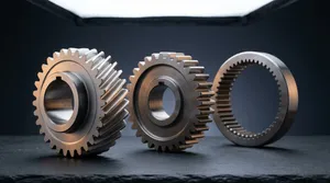
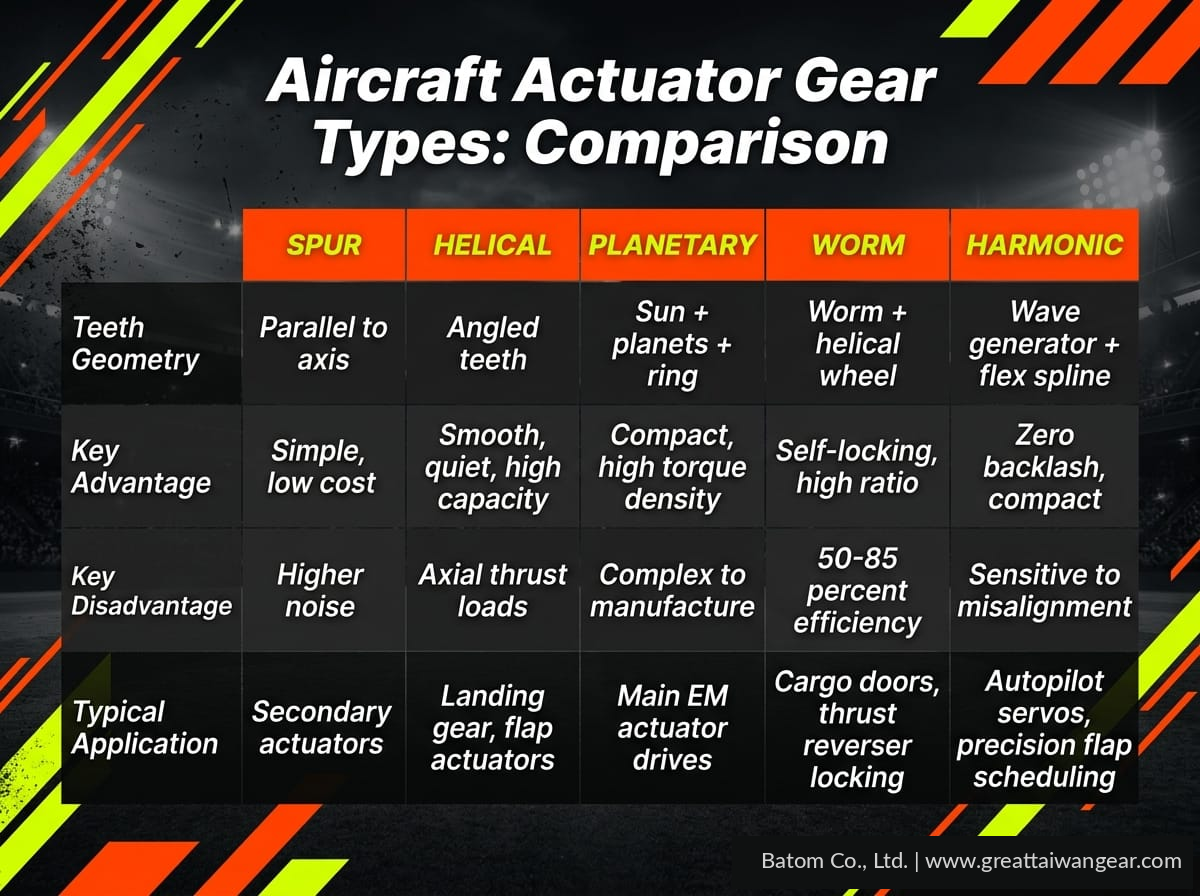
2. Gear Types for Actuator Applications
Spur Gears
Spur gears represent the simplest and lowest-cost gear solution, with teeth parallel to the axis of rotation. They excel in applications requiring straight-line torque transmission at moderate speeds. In actuators, spur gears typically serve as the final drive stage in low-speed, high-torque applications. However, spur gears generate significant mesh noise and produce radial forces that increase bearing loads. In precision applications such as flight control, tooth contact stress can be high due to the concentrated contact pattern along a single line.
Advantages: Simple design, easy manufacturing, low cost, minimal axial thrust Disadvantages: Higher noise, lower load-carrying capacity per size, higher stress concentration Typical Applications: Secondary actuators, gear reduction stages in two-speed systems
Helical Gears
Helical gears incorporate angled teeth that mesh progressively, distributing loads across multiple tooth pairs simultaneously. This results in smoother operation, lower noise, and significantly higher torque capacity compared to spur gears of identical size. The progressive mesh characteristic allows helical gears to absorb shock loads more effectively. However, helical gears generate axial thrust forces that must be accommodated in the bearing design.
Advantages: Smooth engagement, high load capacity, quiet operation, excellent shock absorption Disadvantages: Axial thrust requires thrust bearings, more complex manufacturing Typical Applications: Landing gear retraction, flap actuators, main reduction stages
Planetary Gear Trains
Planetary systems employ a central sun gear, multiple planet gears orbiting around it, and an outer ring gear. This architecture delivers exceptionally high torque density in compact envelopes—ideal for weight-constrained aircraft systems. Planetary stages can achieve speed reduction ratios exceeding 10:1 in a single stage while maintaining concentric input/output shafts. The distributed load across multiple planet gears reduces individual tooth stress and extends fatigue life. Actuator designers frequently employ one or two planetary stages followed by a helical or spur stage to achieve the desired speed and torque characteristics.
Advantages: Compact, high torque density, multiple load paths, high reduction ratios Disadvantages: Complex manufacturing, challenging backlash control, higher cost Typical Applications: Main drive stages in electromechanical actuators, speed multipliers in hydraulic units
Worm Gears
Worm gear sets consist of a threaded worm meshing with a helical worm wheel. The inherent friction in the worm-wheel interface creates mechanical self-locking—when properly designed, the worm wheel cannot backdrives the worm, preventing uncommanded motion under gravity or other external loads. This self-locking characteristic is invaluable in safety-critical applications such as cargo doors and thrust reversers, where loss of actuator power must not result in system failure.
Advantages: Self-locking capability, simple design, high reduction ratios (up to 100:1), safety-critical applications Disadvantages: Higher friction losses (efficiency typically 50-85%), heat generation, lower efficiency Typical Applications: Cargo door actuators, thrust reverser locking, manual backup actuators
Strain Wave Gear Systems
Strain wave gears employ a rotating elliptical wave generator that flexes a thin-walled flexible spline, achieving extremely high speed reduction ratios (50:1 to 320:1) in minimal volume. The design inherently maintains near-zero backlash throughout the service life. Strain wave gears excel in high-accuracy positioning applications requiring submillimeter repeatability.
Advantages: Zero backlash, compact, high reduction ratio, smooth torque delivery Disadvantages: High cost, sensitive to misalignment, limited torque capacity per size Typical Applications: Autopilot servos, precision flap scheduling, advanced flight control systems
3. Design Requirements
Aircraft actuator gears must satisfy demanding performance criteria that reflect the unforgiving nature of flight operations:
Load Ratings
Gears must be rated for both static and dynamic loads. Static load capacity ensures gears can sustain rated torque without permanent deformation or micro-slip. Dynamic load capacity, defined by tooth bending fatigue and surface pitting resistance, must accommodate cyclic stressing over the entire aircraft service life. For flight-critical applications, designers typically apply 1.5× to 2.0× safety factors to rated loads to account for transient spikes and shock loading. Landing gear gears often experience shock factors exceeding 2.5×, requiring material selection and stress analysis to validate safe operation.
Backlash Control
Backlash—the clearance between mating gear teeth—must be minimized in flight control applications to eliminate lost motion and hysteresis. Specifications typically require backlash less than 0.05 mm in rudder and elevator actuators, achieved through tight manufacturing tolerances (typically DIN 6 or better (AGMA A5 or better)) and precision grinding of tooth flanks. Excessive backlash introduces non-linearity in control response, while too-tight backlash can cause gear jam or accelerated wear.
Weight Constraints
Aircraft weight directly impacts fuel consumption and operational range. Actuator designers seek the minimum gear envelope and weight that satisfies torque and fatigue requirements. Material selection (aluminum bronze versus steel), gear ratio optimization, and compact planetary designs all contribute to weight reduction. Some applications employ titanium or composite housings to further reduce parasitic weight.
Operating Temperature Range
DO-160 environmental standards specify operating temperature ranges from -55°C (cruise altitude) to +200°C (engine bay proximity). Gear materials must maintain yield strength and fracture toughness across this range. Lubricants must remain fluid at low temperature and resist oxidation and viscosity loss at high temperature. Material selection shifts toward high-temperature alloys (Pyrowear 53, Inconel 718) in extreme-temperature zones.
Vibration and Shock Resistance
MIL-STD-810 mechanical shock and vibration testing simulates in-service environmental stressing. Gears must withstand random vibration acceleration levels of 10-20 g in flight-critical applications, plus tactical shock pulses of 15-30 g. Gear design must prevent resonance within the operational frequency band while maintaining acceptable stress levels under peak environmental inputs.
Corrosion Resistance
Gears operating in salt-air or moisture-rich environments (particularly in amphibious aircraft or maritime patrol variants) must resist corrosion without compromising mechanical properties. Case-hardened steel gears require protective coatings or material modifications (nickel plating, PVD coatings) to prevent rust. Some designs specify stainless steel (AISI 440C) or nickel-based alloys where corrosion risk is elevated.
Redundancy and Fault Tolerance
Safety-of-flight actuators often employ dual-motor or dual-solenoid designs, ensuring that single-actuator failure does not prevent control surface movement. Some applications utilize mechanical redundancy, such as independent locking systems, to retain control authority even upon catastrophic gear failure. Gear design must prevent fragmentation or seizure modes that could impede backup systems.
4. Material Specifications
AISI 9310 Carburizing Steel
AISI 9310 represents the industry standard for aircraft gears, offering excellent balance of fatigue strength, fracture toughness, and cost-effectiveness. This nickel-chrome-molybdenum steel is carburized to develop a hard, wear-resistant surface case (typical case depth 0.6–1.2 mm, case hardness 58–62 HRC) over a tough core (typical core hardness 35–45 HRC). The core toughness prevents brittle fracture under shock loading, while the case hardness resists tooth pitting and scoring.
Mechanical Properties (typical after carburizing and tempering):
- Tensile Strength: 1,150–1,300 MPa (core)
- Yield Strength: 850–950 MPa (core)
- Core Hardness: 35–45 HRC
- Case Hardness: 58–62 HRC
- Fracture Toughness: 45–55 MPa√m
- Fatigue Limit: 400–500 MPa (bending), 500–600 MPa (contact stress)
Pyrowear 53
Pyrowear 53 is a high-temperature carburizing steel engineered for demanding thermal environments. It maintains excellent case hardness and core toughness at sustained operating temperatures up to 200°C, which makes it the preferred material for actuator gears subjected to prolonged thermal stress from APU bleed air, turbine backwash, or high-duty-cycle braking.
Mechanical Properties (typical):
- Tensile Strength: 1,900–2,050 MPa
- Yield Strength: 1,600–1,750 MPa
- Hardness: 60–62 HRC (carburized case)
- Fracture Toughness: 35–45 MPa√m
- Fatigue Limit: 600–700 MPa (bending), 700–800 MPa (contact stress)
- Temperature Limit: Up to 200°C continuous operation
Inconel 718 (Nickel-Based Superalloy)
Inconel 718 is employed in extreme-temperature zones of turbine engine accessory drives and thrust reverser systems where sustained temperatures exceed 200°C or thermal cycling creates high stress concentrations. This age-hardened nickel-iron-cobalt superalloy maintains excellent creep resistance and fatigue strength at elevated temperatures. However, Inconel 718 gears are expensive and demand specialized manufacturing (EDM finishing, precision grinding), limiting application to high-value systems.
Mechanical Properties (typical at room temperature):
- Tensile Strength: 1,380–1,520 MPa
- Yield Strength: 1,020–1,170 MPa
- Hardness: 40–45 HRC
- Fatigue Limit: 500–600 MPa (bending) at temperature
Titanium Alloys (Ti-6Al-4V)
Titanium alloys are selectively employed in weight-critical applications such as unmanned aerial vehicles (UAVs) or supersonic platforms where every gram of weight reduction improves performance. Ti-6Al-4V offers excellent strength-to-weight ratio and operates reliably up to 300°C. However, titanium is susceptible to galling (cold welding) during gear mesh, requiring specialized surface treatments and judicious gear design.
Mechanical Properties (typical):
- Tensile Strength: 880–1,000 MPa
- Yield Strength: 800–900 MPa
- Density: 4.4 g/cm³ (compared to 7.8 g/cm³ for steel)
- Fatigue Limit: 300–400 MPa (bending)
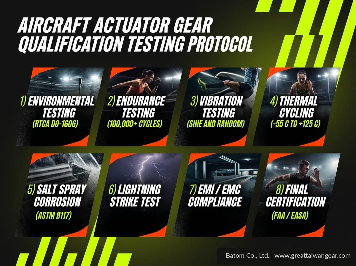
5. Testing Protocols
Actuator gears must survive rigorous qualification testing that simulates the full spectrum of in-service loading and environmental stressing:
DO-160 Environmental Qualification
Aeronautical Radio, Incorporated (ARINC) standard DO-160 establishes environmental qualification requirements for aircraft equipment. Actuator gears and associated components must demonstrate functionality across the specified environmental envelope:
- Temperature: Operational limits from -55°C to +85°C (or +200°C in engine bay applications); equipment must survive storage temperatures to -65°C and +100°C
- Humidity: Equipment must resist moisture in 10–90% relative humidity environment without corrosion or performance degradation
- Altitude: Pressure equivalent to 50,000 feet (10.7 kPa absolute pressure)
- Fungal Resistance: Materials must resist fungal growth per MIL-STD-810
MIL-STD-810 Mechanical Shock and Vibration
U.S. Department of Defense standard MIL-STD-810 provides test methods for mechanical shock and random vibration. Actuator gears and drive units typically undergo:
- Random Vibration: 10–20 g acceleration levels across 20–2,000 Hz frequency range, for duration of 2–4 hours per axis
- Tactical Shock: 15–30 g peak acceleration, 20–50 millisecond duration, applied in multiple directions
- Thermal Shock: Rapid temperature transitions (-55°C to +85°C) to detect cracking or fastener loosening
Endurance Testing
Flight-critical actuators must demonstrate reliability over the anticipated service life. Endurance testing typically specifies:
- Cycle Count: 25,000 to 50,000 complete actuator cycles (full extension and retraction)
- Load Profile: Full rated load applied during each cycle
- Duty Cycle: Intermittent cycling with rest periods to approximate operational duty
- Monitoring: Torque ripple, noise signature, and temperature monitored throughout test
- Acceptance: Zero failures and less than 5% increase in operating torque
HALT/HASS Screening
Highly Accelerated Life Testing (HALT) and Highly Accelerated Stress Screening (HASS) employ combined thermal, vibration, and pressure stressing to rapidly identify latent defects. HALT pushes environmental parameters to failure limits to establish design margins, while HASS applies controlled levels (50–80% of HALT limits) to screen production units for manufacturing defects.
Fatigue Life Testing
Gear tooth fatigue is analyzed using AGMA or ISO methodologies, with finite element analysis (FEA) supporting stress prediction. Physical fatigue testing on back-to-back test rigs (two geared units driving each other) accelerates cycles and detects pitting or scoring that might require millions of operational cycles to manifest. Test rigs operate at elevated speed (typically 1.5–2.0× operational speed) and 110–125% rated torque.
Tooth Contact Pattern Analysis
Prussian blue or electronic contact pattern analysis reveals the actual contact footprint on gear teeth. Proper contact pattern concentrates pressure in the central tooth face, avoiding edge contact that accelerates wear or cracking. Contact pattern assessment during assembly validation and after endurance testing confirms that no distress has migrated the contact zone.
6. Qualification Standards
Aircraft actuator gears must comply with multiple certification and quality management standards to ensure airworthiness:
AS9100 Rev D (Aerospace Systems and Products Certification and Management Standard)
AS9100 Rev D integrates ISO 9001 quality management system requirements with aerospace-specific requirements including:
- Configuration management and traceability of design changes
- Foreign object damage prevention
- Tool and equipment calibration traceable to NIST standards
- Work instructions with aerospace-specific clauses
- First-article inspection (FAI) requirements
Gear manufacturers must maintain AS9100 Rev D certification to supply OEMs directly, with audit frequencies determined by audit risk assessment.
Nadcap Special Process Qualification
Nadcap (National Aerospace and Defense Contractors Accreditation Program) accreditation is required for critical special processes including:
- Heat Treatment: Carburizing, hardening, and tempering processes for AISI 9310 and other alloys
- Non-Destructive Testing (NDT): Magnetic particle inspection (MPI), liquid penetrant testing (LPT), ultrasonic testing (UT) to detect surface and subsurface defects
Nadcap technical specialists audit heat treating facilities and NDT laboratories to verify process control, calibration, and operator qualification.
FAA PMA (Parts Manufacturer Approval) and EASA Part 21
Parts Manufacturer Approval (FAA PMA) authorizes manufacturers to produce replacement parts for FAA-approved products. EASA Part 21 provides equivalent European Union certification. Both require:
- Technical data package including design drawings, material specifications, and test reports
- Demonstration of design and manufacturing capability through first-article inspection
- Quality system audit and surveillance
- Traceability of all materials and processes to specification
PPAP/FMEA Requirements
Production Part Approval Process (PPAP) requires suppliers to demonstrate that manufacturing processes consistently produce parts meeting design specifications. Failure Modes and Effects Analysis (FMEA) identifies potential failure modes, their causes, effects, and mitigation strategies. FMEA is integral to design review and manufacturing process planning, with severity ratings (1–10 scale) prioritizing risk mitigation for high-severity failure modes.
7. Failure Modes and Reliability
Understanding potential failure modes and their mitigation strategies is essential for robust gear design:
Tooth Fatigue
High-cycle fatigue of gear teeth occurs when bending stress cycles exceed the material's fatigue limit. Surface-initiated cracks propagate from stress concentrations at the tooth root, eventually fracturing the tooth. Tooth fatigue is mitigated through:
- Optimization of tooth fillet radius to reduce stress concentration
- Selection of material with adequate core fatigue strength
- Control of residual stress through shot peening (compressive residual stress delays crack initiation)
- Conservative design allowable stresses (typically 50–60% of theoretical fatigue limit)
Pitting and Scoring
Contact fatigue and sliding friction at the gear mesh cause surface distress:
- Pitting: Subsurface-initiated fatigue cracks propagate to the surface, releasing material fragments and creating small pits. Progressive pitting accelerates as stress concentrates at pit edges.
- Scoring: Boundary lubrication or inadequate film thickness causes asperity contact and metal-to-metal sliding, leaving fine scratches or gouges on the tooth flank.
Prevention strategies include:
- Material selection with high contact fatigue strength
- Precision grinding of tooth flanks to reduce surface roughness
- Lubricant viscosity and additives optimized for the operating speed and load
- Case depth adequate to prevent case-spalling
Case Crushing (Peeling)
In carburized gears, severe contact stress or inadequate case depth can exceed the shear strength of the case, causing it to crush or peel away from the core. Once the hard case is compromised, the softer core is exposed to contact stress it cannot support, leading to rapid deterioration. Prevention requires:
- Adequate case depth (typically 0.8–1.2 mm for aircraft gears)
- Conservative contact stress allowables (typically 1,200–1,400 MPa for AISI 9310)
- Proper material selection for extreme-temperature applications (Pyrowear 53, Inconel 718)
MTBF and Reliability Targets
Flight-critical actuators typically specify mean time between failure (MTBF) exceeding 50,000 operational hours, with reliability targets of 0.99 (99% probability of operation without failure over the specified mission profile). Reliability is demonstrated through:
- Physics-of-failure analysis predicting failure rates from stress and material properties
- Weibull statistical analysis of field data and test results
- Fault tree analysis (FTA) quantifying system reliability from component reliabilities
- Redundancy and failsafe design to tolerate single-component failures
8. Supplier Evaluation for Actuator Gears
Selecting a qualified supplier is critical to achieving design specifications and certification requirements:
Equipment Capability
Evaluate the supplier's manufacturing equipment for:
- CNC Gear Hobbing Machines: Precision multi-axis equipment for high-volume production with tool offset compensation and automated measurement
- Grinding and Honing: Precision finishing equipment to achieve DIN 6 or finer (AGMA A5 or finer) surface finish and tight tooth spacing tolerances
- Heat Treat Facilities: Controlled-atmosphere furnaces with continuous monitoring of temperature, carbon potential, and quench oil condition
- Inspection Equipment: Coordinate measuring machines (CMMs), gear rolling testers, tooth contact pattern analyzers, and non-destructive testing (NDT) equipment
Certification Status
Verify current certifications:
- AS9100 Rev D: Current and unrestricted (check audit dates and any restrictions)
- Nadcap Accreditation: Current for heat treatment and relevant NDT methods
- ISO 9001:2015: Quality management system certification
- Customer Approvals: FAA PMA, EASA Part 21, or equivalent approval for relevant aircraft platforms
Process Control
Examine supplier's statistical process control (SPC) programs:
- In-process Monitoring: Real-time measurement and charting of critical dimensions
- Material Traceability: Full documentation of material source, lot number, and chemical composition testing
- First-Article Inspection (FAI): Detailed measurement and testing of first production units before full-rate production
- Trend Analysis: Regular review of capability indices (Cpk, Ppk) to detect process drift
Lot Traceability and Genealogy
Aircraft-quality suppliers maintain genealogy records linking each component to:
- Raw material lot and source
- Manufacturing process parameters (feed rate, speed, cutting tool ID)
- Heat treatment cycle parameters and furnace records
- Final inspection and test data
- Inspection authority sign-off and date
Taiwan Advantage
Taiwan has emerged as a global center for precision gear manufacturing, combining:
- Cost Advantage: Labor and facility costs 20–40% lower than U.S. or European suppliers while maintaining equivalent quality
- Quality Reputation: Decades of aerospace supply chain participation have established Taiwan manufacturers as reliable, AS9100-certified partners
- Manufacturing Flexibility: Taiwan's manufacturing ecosystem supports both high-volume production and low-rate, high-mix production common in aerospace
- Lead Time Management: Geographic proximity to raw material suppliers and established logistics networks support predictable delivery schedules
- Technical Expertise: Taiwan's gear industry benefits from deep knowledge of carburizing, grinding, and precision measurement accumulated over multiple generations
Conclusion
Aircraft actuator gears represent a critical intersection of precision manufacturing, materials engineering, and safety-critical design. Meeting the stringent design requirements, testing protocols, and qualification standards demands expertise across multiple disciplines and commitment to continuous quality improvement. Whether designing flight control actuators, landing gear systems, or engine accessory drives, engineers must leverage advanced materials, precision manufacturing, and rigorous testing to ensure reliable, safe operation throughout the aircraft's service life.
Selecting a qualified supplier with proven AS9100 and Nadcap certifications, robust process control, and deep aerospace experience is essential to achieving program objectives and certification milestones. Taiwan-based manufacturers have established a strong track record of delivering high-quality actuator gears to global aerospace OEMs, combining cost-effectiveness with reliability and technical expertise.
Frequently Asked Questions
Q1: What backlash limit should I specify for flight control gears?
A: Flight control gears typically require backlash less than 0.05 mm to minimize hysteresis and lost motion in control response. This is achieved through DIN 6 (AGMA A5) precision grade manufacturing and careful assembly procedures. Your gear supplier should provide backlash certification data for each production lot.
Q2: Which material is best for high-temperature actuator gears operating above 150°C?
A: For sustained temperatures above 150°C, Pyrowear 53 high-temperature carburizing steel is the preferred choice, offering stable properties to 200°C. Inconel 718 is specified for extreme temperature zones exceeding 200°C in turbine engine applications, though cost and manufacturing complexity limit its use. AISI 9310 carburized steel is suitable to approximately 120°C sustained operation.
Q3: How do I verify that a gear supplier maintains adequate process control?
A: Request the supplier's capability study data (Cpk and Ppk indices) for critical dimensions, control plans showing in-process measurement frequency, and SPC charts for the past 12 months. Require first-article inspection (FAI) per AS9100 standards and conduct periodic second/third-article inspections during production. Visit the supplier's facility to audit CMM calibration, heat treat documentation, and NDT equipment certification.
Q4: What is the typical cost difference between AISI 9310 and Pyrowear 53 actuator gears?
A: Pyrowear 53 gears typically cost 2.5–3.5× more than equivalent AISI 9310 gears due to its specialized alloy composition and the demanding high-temperature heat treatment and carburizing process control it requires. The cost premium is justified only when sustained high-temperature operation (>150°C) or enhanced fatigue strength is required. For standard flight control and landing gear applications, AISI 9310 remains the cost-effective choice.
Q5: How is gear reliability quantified in FMEA and fault tree analysis?
A: Gear reliability is assessed using physics-of-failure models predicting wear and fatigue rates from Hertzian contact stress and bending stress, combined with material fatigue properties and residual stress effects. Weibull analysis of failure test data or field data establishes failure rate distributions. Fault tree analysis quantifies system reliability as the probability that all gears and redundant systems function throughout the mission profile, typically targeting reliability ≥0.99 (99%) for flight-critical functions.
About Batom Co., Ltd.
Batom Co., Ltd. is a Taiwan-based precision gear manufacturer specializing in aerospace-grade actuator gears, power transmission components, and complex gear assemblies for global OEMs. With AS9100 Rev D and Nadcap certifications, Batom delivers materials including AISI 9310, Pyrowear 53, and Inconel 718 gears manufactured to DIN 6 (AGMA A5) precision standards. Our facility combines advanced CNC hobbing, precision grinding, and controlled-atmosphere heat treating to meet the most demanding aerospace qualification requirements.
Contact Batom Co., Ltd. for your next actuator gear project: Contact Batom