
Cobot Joint Gears: Design Challenges, Torque Requirements & Material Choices
Introduction: The Collaborative Robot Revolution
The collaborative robot (cobot) market has experienced explosive growth over the past five years, with projections indicating the market will exceed USD 12 billion by 2030. This growth reflects the fundamental shift in manufacturing toward flexible, human-safe automation. However, the success of cobots hinges critically on one often-overlooked component: the precision gear systems at the heart of each joint.
At Batom Co., Ltd., we understand that cobot joint gears represent far more than simple mechanical components. They are the precision enablers that determine whether a cobot can safely collaborate with humans, perform delicate assembly tasks, or adapt to changing production requirements. This comprehensive guide explores the complex engineering challenges, technical specifications, and material science behind modern cobot joint gear systems.
Market Drivers: Why Cobot Gear Demand Is Surging
The collaborative robot market growth is driven by several interconnected factors:
Manufacturing Labor Shortage: With aging populations in developed nations and rising labor costs, manufacturers increasingly turn to cobots for tasks ranging from assembly to material handling. Unlike traditional industrial robots confined to isolated cells, cobots work alongside humans—demanding inherently safer, more responsive designs.
Industry 4.0 Adoption: Modern factories require rapid reconfiguration for varied production runs. Cobots offer flexibility that fixed automation cannot match, but this flexibility depends on sophisticated joint control enabled by precision gearing.
Supply Chain Resilience: Manufacturers worldwide are diversifying supply chains and reshoring production. Regional cobot manufacturing facilities require local suppliers of high-precision components. Taiwan-based manufacturers like Batom are positioned perfectly to serve this demand.
Technological Breakthroughs: Advances in sensor technology, force/torque control algorithms, and materials science have made true human-robot collaboration technically feasible. Precision gears enable the responsive control systems that make this collaboration safe.
Cobot Joint Architecture: The Six (or Seven) Degrees of Freedom
A typical collaborative robot features a 6 or 7 degree-of-freedom (DOF) design:
- J1 (Base Rotation): Horizontal rotation about the robot's base
- J2 (Shoulder Pitch): Vertical movement of the upper arm
- J3 (Elbow Pitch): Elbow joint, extends arm reach
- J4 (Wrist Rotation): First wrist joint, rotates end-effector
- J5 (Wrist Pitch): Wrist vertical movement
- J6 (Tool Rotation): End-effector rotation
Optional J7: Wrist Rotation 2 (found on select 7-DOF designs for enhanced dexterity)
Each joint incorporates a gearbox that reduces high-speed motor output to lower speeds with dramatically increased torque. The characteristics of these gearboxes—their backlash, efficiency, size, and durability—directly impact the cobot's capabilities.
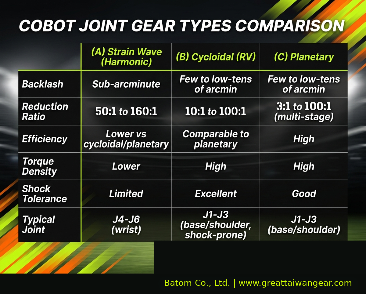
Comparative Analysis of Cobot Gear Types
Modern cobots typically employ a combination of three primary gear reduction technologies. Each offers distinct advantages and trade-offs.
Strain Wave Gear Reducers: The Precision Solution
Note on terminology: throughout this article we use the generic engineering term "strain wave gear(s)" for the wave-generator / flexspline / circular-spline reduction technology. "Harmonic Drive®" is a registered trademark of Harmonic Drive Systems Inc. and is one commercial implementation of this technology; we use the generic term to keep the discussion vendor-neutral.
Operating Principle: Strain wave gears (often commercially referred to as harmonic drives) employ a remarkable mechanism: a flexible metallic wave generator cyclically deforms a thin-walled flexspline, which meshes with a rigid circular spline, creating a rolling wave that reduces speed and increases torque. The mechanism has very low theoretical backlash.
Typical Performance Range (application-dependent — actual figures depend on size, ratio, manufacturer, and operating envelope):
- Backlash: typically sub-arcminute
- Reduction ratio: typically 50:1 to 160:1
- Efficiency: typically lower than planetary or cycloidal designs (friction in the wave-generator / flexspline interface)
- Compactness: very compact, with low component count (wave generator + flexspline + circular spline)
Advantages:
- Very high precision for assembly and force-control applications
- Compact form factor that suits the wrist of a cobot
- Very low backlash reduces cumulative positioning errors
- Smooth operation with low torque ripple
Disadvantages:
- Higher unit cost than planetary alternatives, with the price scaling by size and ratio
- Lower torque density than planetary or cycloidal designs
- More susceptible to damage from mechanical shock
- Smaller margin for high-load or impact-prone joint positions
- Flexspline fatigue is the dominant life-limiting failure mode (see flexspline material section below)
Ideal Applications:
- Wrist joints (J5, J6) where precision is paramount
- Fine assembly operations requiring <0.1mm repeatability
- Force/torque control applications where backlash degrades feedback
Common applications: commonly used in cobots from a number of leading manufacturers worldwide; specific OEM configurations vary and should be confirmed against publicly available product datasheets rather than inferred from this article
Planetary Gear Reducers: The Torque Workhorse
Operating Principle: Planetary gear systems feature a central sun gear orbited by planet gears, all contained within a ring gear. As the planet carrier rotates, the planet gears orbit while meshing with both sun and ring gears, creating smooth, high-torque transmission.
Typical Performance Range (application-dependent):
- Backlash: typically a few to low-tens of arcminutes, with tighter values achievable through preloaded or anti-backlash designs
- Reduction ratio: typically 3:1 to 100:1 in multi-stage designs
- Efficiency: typically high (well-suited for sustained operation)
- Torque density: high — significant torque in a compact envelope
- Precision grade: ISO 1328 grades comparable to AGMA A4–A6 are achievable with proper manufacturing (cross-standard equivalence is broadly aligned, not 1:1)
Advantages:
- Excellent torque density ideal for base and shoulder joints
- Superior heat dissipation for continuous operation
- Mature technology with proven reliability records
- Cost-effective at scale
- Service-friendly with modular components
- Better shock absorption than strain wave gears
Disadvantages:
- Backlash control more challenging than strain wave gears
- More moving parts mean higher maintenance potential
- Multi-stage designs can be heavier
- Noise generation slightly higher than strain wave gears
Ideal Applications:
- Base joint (J1) supporting entire robot weight
- Shoulder joints (J2, J3) bearing significant payload
- Tasks where cost-efficiency matters more than absolute precision
- Heavy-duty manipulation requiring sustained torque
Common applications: widely used at the base, shoulder, and elbow joints of mid-payload cobots from several major OEMs
Cycloidal Reducers: The Shock-Resistant Alternative
Operating Principle: Cycloidal reducers employ specially-shaped cycloidal discs that mesh with an offset input member and a stationary pin array. The geometry creates a unique rolling-sliding motion that progressively engages and disengages, resulting in exceptionally smooth power transmission.
Typical Performance Range (application-dependent):
- Backlash: typically a few to low-tens of arcminutes, improvable through precision manufacturing
- Reduction ratio: typically 10:1 to 100:1
- Efficiency: typically comparable to planetary designs
- Shock resistance: well-suited to sudden load spikes
- Smoothness: progressive gear engagement gives smooth power transmission
Advantages:
- Superior shock and impact resistance
- Smooth operation critical for human collaboration
- High efficiency supports extended duty cycles
- Excellent for tasks involving sudden load changes
- Good torque transmission efficiency
Disadvantages:
- Backlash control more difficult than strain wave gears
- Manufacturing tolerances are critical and demanding
- Fewer global suppliers limit options
- Maintenance requires specialized knowledge
- Component complexity matches planetary systems
Ideal Applications:
- Spot welding robots where impact resistance matters
- Material handling tasks involving sudden load changes
- Collaborative tasks where smoothness is essential for human safety
- Manufacturing environments where shock loads are inevitable
Common applications: increasingly seen in shock-prone joint positions and in higher-payload cobot designs
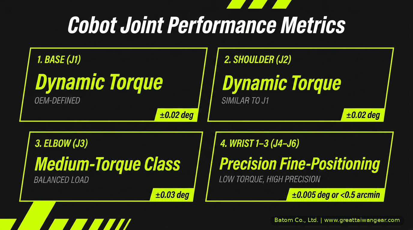
Detailed Torque Analysis by Joint Position
Understanding the torque requirements at each joint position is essential for proper gearbox selection and material specification.
J1 (Base Rotation) — High-Torque Class
J1 (Base Rotation) must withstand substantial dynamic moments that often far exceed the static load contribution alone, especially in mid-payload cobots with long reach. The design target is set by the robot OEM's payload-and-reach envelope and dynamic-motion profile, not by static analysis alone.
Design Considerations:
- High continuous torque requirement
- Thermal management critical
- Bearing selection must accommodate radial loads from arm weight
- Reduction ratio: typically 50:1 to 100:1, application-dependent
- Typical gear type: planetary or multi-stage cycloidal — strain wave gears are generally not the first choice at J1 because base joints prioritize torque density and shock tolerance
- Material: 20CrMnTi alloy steel, case-carburized to a typical gear-tooth hardness class
J2 (Shoulder Pitch) — High-Torque Class
The shoulder joint elevates and lowers the arm. While not bearing the full weight (base joint supports most), it must provide precise control of a substantial cantilevered load. Typical torque target is on the order of 100–200 N·m, application-dependent and set by the robot OEM's payload-and-reach envelope.
Design Considerations:
- High torque, significant positioning precision
- Thermal load from continuous operation
- Must maintain positioning accuracy under thermal expansion
- Recommended Reduction Ratio: typically 50:1 to 80:1, application-dependent
- Typical Gear Type: planetary or cycloidal — these are the more common choice for high-torque shoulder positions; strain wave gears are generally less suitable here because their torque density and shock tolerance are lower than planetary/cycloidal designs
- Material: 42CrMo alloy steel, surface-hardened to a typical gear-tooth hardness class
J3 (Elbow Pitch) — Medium-Torque Class
The elbow extends or retracts the end-effector. Load decreases significantly as we move along the kinematic chain.
Design Considerations:
- Moderate torque with dynamic precision requirements
- Faster response times reduce gearbox thermal load
- Backlash becomes increasingly important for precision
- Recommended Reduction Ratio: 40:1 to 60:1
- Typical Gear Type: Planetary or high-precision planetary
- Material: 42CrMo alloy steel, 54-57 HRC hardness
J4 (Wrist Rotation) — Precision Class
The first wrist joint begins the precision-critical region. Load decreases significantly, but precision requirements increase.
Design Considerations:
- Moderate torque, high precision demand
- End-effector orientation control critical
- Thermal load minimal due to light loads
- Backlash <1 arcmin increasingly important
- Recommended Reduction Ratio: 30:1 to 50:1
- Typical Gear Type: Strain wave gear or high-precision planetary
- Material: 42CrMo alloy steel or 20CrMnTi, surface-hardened
J5 (Wrist Pitch) — Fine-Positioning Class
The wrist pitch provides vertical orientation control. This joint frequently requires high-precision backlash specifications.
Design Considerations:
- Lower torque, highest precision demands
- Critical for fine assembly operations
- Responsive to force/torque feedback
- Backlash <0.5 arcmin often required
- Recommended Reduction Ratio: 20:1 to 40:1
- Typical Gear Type: Strain wave gear (standard choice)
- Material: 42CrMo alloy steel or titanium alloy for weight
J6 (Tool Rotation) — Low-Torque, Fine-Positioning Class
The end-effector rotation is a low-torque, high-precision joint. Some applications may use direct-drive motors or minimal reduction.
Design Considerations:
- Minimal torque requirement
- Extremely tight backlash specifications <0.3 arcmin
- Weight critical (furthest from base)
- Compact form factor essential
- Recommended Reduction Ratio: 10:1 to 20:1
- Typical Gear Type: Strain wave gear or compact planetary
- Material options may include high-strength aluminum alloys, titanium alloys, or surface-hardened steels (such as 38CrMoAl, nitrided), depending on the required inertia, rigidity, and payload profile
Backlash Requirements and Precision Control
Backlash—the play or "slop" between meshing gear teeth—represents perhaps the most critical specification for cobot gears. The requirement of <1 arcminute (1/60th of a degree, or approximately 0.0003 radians) stems from several application demands.
Fine Assembly Tasks
Electronics manufacturing frequently requires part placement accuracy of <0.1mm. A robot with 300mm reach and 1 arcminute backlash experiences 0.087mm positional uncertainty per joint. With six joints in series, cumulative backlash could exceed acceptable tolerances.
Mitigation strategies:
- Strain wave gear selection for critical joints
- Dual-motor configurations with closed-loop feedback
- Backlash compensation algorithms in controller software
Force Control and Compliance
Robots performing tasks like assembly insertion or surface finishing must sense and respond to environmental forces. Excessive backlash decouples the force sensor feedback from actual end-effector interaction, degrading control stability.
Impact: Force control bandwidth decreases dramatically with backlash. A joint with 5 arcminute backlash operates safely only at <10 Hz control frequencies, while <1 arcminute systems support 50+ Hz control.
Human-Robot Collaboration Safety
Cobots employ force/torque sensing to detect unintended collisions and respond appropriately. Backlash creates "dead zones" where applied force doesn't immediately generate feedback signal, potentially delaying safety responses.
Safety implication: Cobots with <1 arcminute backlash respond to collision detection within 10-20 milliseconds, meeting ISO/TS 15066 safety standards for collaborative operation.
Weight Constraints: The Lightness Imperative
Joint gearboxes must maximize torque density (torque-to-weight ratio) to keep overall cobot mass reasonable. Optimizing the mass of J4–J6 is particularly critical to reduce the moment of inertia on the base joints (J1–J3) and to keep dynamic loads within the OEM's payload-and-reach envelope.
Weight optimization strategies:
Aluminum Housing: Aluminum alloy (typically 6061-T6) housings reduce weight by 40-50% compared to cast iron, at the cost of slightly lower thermal conductivity.
Titanium Components: Selective use of titanium in high-stress pinion shafts reduces weight while maintaining strength.
Composite Materials: Carbon-fiber reinforced plastic housings reduce weight further, acceptable where thermal loads are minimal (wrist joints).
Careful Bearing Selection: Angular contact bearings optimized for the specific load case eliminate oversizing.
Design Optimization: Topology optimization software identifies material-efficient designs that maintain rigidity while minimizing mass.
Noise Requirements: Enabling Human Collaboration
Cobots operating in human environments must meet strict noise limits. General occupational safety guidelines and cobot ergonomic considerations, along with standards such as ISO/TS 15066 and ISO 10218-1/2, typically encourage lower operating noise levels for improved worker comfort. Individual joint gearbox targets are set by the OEM's overall acoustic envelope, with margin reserved for motor and structural noise.
Noise Generation Mechanisms
Gear Mesh Excitation: As teeth engage and disengage, they transfer impact forces creating acoustic vibration. Surface finish and precision directly control this mechanism.
Bearing Noise: Rolling element bearings generate noise, particularly under heavy loads. Selection and preload significantly impact performance.
Resonance Amplification: Gearbox housings can resonate at specific frequencies. Damping material and structural design control resonance.
Noise Reduction Techniques
Tooth Profile Modification: Soft modification (gradual relief near tooth flanks) reduces impact forces by 50-70%, dramatically reducing noise without sacrificing strength.
Surface Finish Control: Gear grinding to achieve Ra 0.2–0.4 micrometers reduces micro-slip and high-frequency excitation at the tooth flank.
Precision Manufacturing: DIN 7 or better precision reduces pitch errors that excite resonant frequencies.
Acoustic Damping: Viscoelastic damping materials applied to gearbox walls absorb acoustic energy, particularly effective for frequencies >500 Hz.
Lubrication Optimization: Optimized lubrication strategies using application-specific high-performance greases or synthetic gear lubricants help reduce boundary friction, wear, and noise in robotic transmissions.
Material Selection: The Foundation of Performance
Material choice determines nearly all mechanical properties of cobot gears. The selection process requires balancing strength, wear resistance, fatigue life, cost, and manufacturing capability.
Strain Wave Gear Flexspline: Material and Fatigue Considerations
The flexspline in a strain wave gear is the most fatigue-critical part in the entire cobot drivetrain. As the wave generator rotates, every point on the flexspline wall undergoes continuous high-frequency cyclic elastic deformation — bending in and out millions of cycles per service life. The dominant failure modes are not wear but rather:
- Fatigue cracking at the tooth root or flexspline wall — driven by reversed bending stresses
- Plastic deformation or fatigue-induced shape loss — may occur if peak operational stresses or repeated cyclic loading exceed the material's elastic limit and fatigue resistance
- Heat-treatment distortion — out-of-round flexspline geometry that compromises tooth contact and accelerates fatigue
Material selection for the flexspline therefore optimizes for ultra-high fatigue strength rather than peak hardness. Typical choices include:
- Vacuum Arc Remelted (VAR) specialized alloy steels such as SNCM439 (Ni-Cr-Mo gear steel, JIS designation; broadly comparable to AISI 4340) — VAR processing reduces non-metallic inclusions that act as fatigue-crack initiation sites
- Precipitation-hardening stainless steels such as 15-5PH — used where corrosion resistance and high fatigue strength must coexist
- Both grades require strict heat-treatment controls (vacuum hardening, controlled tempering, stress-relief, and post-process geometry verification) to prevent the distortion and residual-stress patterns that cause premature fatigue failure
This is the primary reason high-quality strain wave gears command a price premium: the flexspline itself carries the durability burden of the entire reducer.
High-Load Joints (J1-J3): Specialty Alloy Steels
20CrMnTi is a widely used cost-effective case-hardening steel in Asian supply chains, while SAE 9310 and 18CrNiMo7-6 are premium nickel-alloyed case-hardening steels commonly specified by Western aerospace and robotics OEMs. The base composition and heat-treatment guidance below applies broadly across this family of carburizing steels.
20CrMnTi (Asia) / SAE 9310 / 18CrNiMo7-6 (Western premium):
- Carbon Content: ~0.2%
- Chromium Content: ~1.2% (promotes hardenability)
- Manganese Content: ~0.8% (improves strength)
- Molybdenum Content: ~0.1% (optional, enhances toughness)
Processing: Case carburizing and quenching
- Case Depth: 0.8-1.2mm
- Case Hardness: 58-62 HRC
- Core Hardness: 35-45 HRC
- Core Toughness: Maintained through controlled hardness gradient
Performance Characteristics:
- Excellent fatigue strength from compressive residual stress in case
- High surface hardness resists scuffing and pitting
- Tough core absorbs shock loads
- Proven in aerospace and high-performance automotive applications
Cost Consideration: Approximately 2-3x cost of mild steel, justified by superior durability.
Medium-Load Joints (J4-J5): Tempered Alloy Steels
42CrMo (or equivalent SAE 4340):
- Carbon Content: ~0.42%
- Chromium Content: ~1.0%
- Molybdenum Content: ~0.2%
Processing: Quenching and tempering, followed by precision surface hardening (e.g., induction hardening or nitriding).
- Surface Hardness: 50–55 HRC at surface (induction hardening) / 600–900 HV (nitriding); core hardness 28–35 HRC from prior Q&T
- Strength: Tensile strength ~1,500 MPa
- Ductility: Elongation ~10%, supporting reliability
Performance Characteristics:
- Balanced strength and ductility
- Excellent machinability enabling precision manufacturing
- Good corrosion resistance in clean environments
- Standard material for precision gearboxes worldwide
Cost Consideration: Moderate cost, excellent value-to-performance ratio.
Light-Load Joints (J6): Diverse Material Options
38CrMoAl (Nitrided):
- Surface nitriding creates exceptionally hard, thin surface layer (0.3-0.5mm)
- Core remains tough despite high surface hardness
- Cost-effective for smaller gears
Titanium Alloys (Ti-6Al-4V):
- Weight reduction 40-50% compared to steel
- Exceptional strength-to-weight ratio
- High cost limits use to weight-critical applications
Engineering Plastics (POM, PPA, PEEK):
- Self-lubricating properties reduce friction and noise
- Lightweight and cost-effective
- Limited to very low-load applications, and typically not the first choice for high-precision cobot wrist gears — used only where the OEM has validated the load profile and payload envelope
Note on J6 material selection: material options may include high-strength aluminum alloys, titanium alloys, surface-hardened steels, or composite materials paired with metallic structural elements. Suitability depends on the specific cobot model, dynamic load profile, and required inertia / rigidity — the choice should be validated case-by-case rather than defaulted to plastic.
Life-Cycle Requirements: Design for Extended Service
Service-life targets for cobot joint gears are application-dependent and set by the OEM clinical / industrial specification — typical targets are in the multi-tens-of-thousands-of-hours range, but the actual figure varies by duty cycle, payload, and operating environment.
Contact and Bending Stress Analysis
Contact & Bending Fatigue Sizing: Modern cobot gear sizing is performed using advanced AGMA / ISO standard calculations for surface (contact) and root (bending) fatigue — for example, ISO 6336 (Calculation of load capacity of spur and helical gears) for cylindrical gear stages. These standards explicitly account for application factor, mesh load distribution, dynamic effects, size, and material properties, and they are the appropriate reference for any production design — rather than reproducing simplified one-line formulas which can be misread or misapplied across reducer types.
Design targets:
- Contact (surface) stresses kept comfortably below the carburized-tooth pitting limit, which is heat-treat- and material-specific.
- Bending stresses maintained strictly below the material's high-cycle fatigue endurance limit, which is highly material- and heat-treat-specific, to support long-life operation.
Fatigue Life Estimation
Modified Miner's Rule: Cumulative damage calculation for variable-load applications accounts for dynamic duty cycles:
Cumulative Damage = Σ(n_i / N_i)
Where:
- n_i: Number of cycles at stress level i
- N_i: Allowable cycles at stress level i
Safety Factor: Carefully optimized for cobot applications to balance weight constraints, stiffness, and fatigue life under the OEM's specific duty-cycle and payload envelope.
Industry Architectural Trends
Rather than naming specific OEMs, the patterns below describe cobot-joint architectural strategies that are visible across the broader collaborative-robotics market. Each represents a different way of balancing torque density, compactness, repeatability, back-drivability, compliance, and human-safety interaction — the value proposition of a cobot is not simply "higher precision" but the engineering balance between these competing requirements.
Hybrid Reducer Architecture (mixed strain-wave + planetary, sometimes cycloidal): the most common pattern in mid-payload 6-DOF cobots. Planetary or cycloidal stages handle the high-torque, shock-prone base / shoulder / elbow joints; strain-wave stages handle the precision-critical wrist (J5 / J6). This approach optimizes torque density and shock tolerance at the base while preserving sub-arcminute repeatability at the tool flange.
Full Strain-Wave Architecture: some lightweight, lower-payload cobots use strain-wave reducers at every joint to maximize repeatability, compactness, and zero-backlash performance across the entire kinematic chain — at the cost of lower torque density and higher unit cost per joint. Better suited to assembly, electronics, and lab-automation duty cycles than to heavy material handling.
Integrated / Modular Joint Architecture: a growing trend toward fully integrated joint modules that combine motor, encoder, brake, force/torque sensing, and reducer in a single sealed unit. This simplifies cabling and integration, improves protection ratings, and supports tighter back-drivability and compliance control. The reducer choice inside an integrated joint is design-specific and typically not exposed at the OEM datasheet level.
Across all three patterns, the engineering objective is the same: deliver the torque density, compactness, repeatability, back-drivability, compliance, and safety-interaction characteristics needed for collaborative operation, while staying within the OEM's payload-and-reach envelope and the relevant safety standards (ISO/TS 15066, ISO 10218-1/2).
Taiwan Supplier Positioning: Strategic Advantages
Taiwan's precision gear manufacturing sector represents a unique strategic advantage for the global cobot industry.
Technical Excellence Foundation
Taiwan gear manufacturers have accumulated:
- Decades of continuous innovation across the cluster: from watch components to aerospace systems
- Complete supply chain ecosystem: Raw material suppliers, heat treat specialists, assembly integrators
- OEM relationships: Direct experience supplying major global robotics manufacturers
Cost-Competitive Manufacturing
Labor Cost Advantage: Highly competitive cost structures and strong total cost of ownership advantages versus traditional Western and Japanese supply chains.
Scale Efficiency: Taiwan's role as the world's leading precision component supplier enables economies of scale unavailable to smaller competitors.
Material Supply: Strategic raw material partnerships with global suppliers ensure quality feedstock at competitive pricing.
Innovation and Customization
Design for Manufacturability (DFM): Taiwan manufacturers offer deep expertise in optimizing gear designs for efficient production and consistent quality, supporting the OEM design team from concept through production.
Agile Prototyping: streamlined processes from design approval to sample gears enable quick validation of new components, with lead times competitive against traditional Western and Japanese supply chains.
Custom Solutions: Willingness to develop proprietary designs for specific applications differentiates Taiwan suppliers from commodity competitors.
Supply Chain Resilience
Post-COVID supply chain restructuring has increased emphasis on geographic diversification. Taiwan-based suppliers offer:
- Alternative sourcing for companies concerned about China-Taiwan tensions
- Closer partnerships with regional manufacturers (Southeast Asia)
- Established quality systems including ISO 9001 and automotive-grade statistical process controls aligned with IATF 16949:2016, providing confidence in high-volume consistency and traceability
Design Challenges and Engineering Considerations
The seemingly straightforward task of specifying a cobot joint gearbox actually presents numerous engineering challenges that separate successful products from mediocre ones.
Thermal Management Under Continuous Operation
Cobots operating at 100% duty cycle (running continuously) generate substantial thermal load in gearboxes. For a typical cobot:
- Motor input power: 200-300W per joint (for larger joints)
- Gear efficiency: 85-90%
- Heat generation: 30-50W per joint (6 watts in base joint alone)
- Passive cooling from metal housing: Limited to ~2-3W/°C
Challenge: Maintaining gearbox temperatures <80°C without active cooling in cramped joint spaces.
Solutions Employed:
- Optimized lubricant selection balancing viscosity and heat dissipation
- Aluminum housings increase surface area and thermal conductivity
- Strategic venting allows ambient air circulation
- Duty cycle restrictions (specified as percentage, not continuous)
Precision Maintenance Across Temperature Range
Cobots operate in environments ranging from -10°C to +50°C. Thermal expansion of steel differs from aluminum, potentially introducing unwanted preload changes in bearings.
Coefficient of Linear Expansion (CTE):
- Steel: 12 × 10⁻⁶ /°C
- Aluminum: 23 × 10⁻⁶ /°C
A 60°C temperature change in an aluminum housing with steel gear creates differential expansion of 0.66 × 10⁻³. For a joint with 100mm diameter, this represents 0.066mm dimensional change—potentially significant.
Solutions:
- Thermal FEA analysis predicts stress distribution and preload changes
- Material selection (matching CTE when possible)
- Bearing preload designed with thermal expansion margin
Backlash Control in Manufacturing
Achieving <1 arcminute backlash consistently in production requires:
Precision Manufacturing:
- Gear tooth spacing tolerance: <0.02mm
- Center distance tolerance: <0.01mm
- Gear bore concentricity: <0.005mm
- Bearing bore tolerance: IT6-IT7 grade
Process Control:
- SPC (statistical process control) on critical dimensions
- 100% backlash measurement on final assembled gearboxes
- Sorting and selective assembly for strain wave gear components
Cost Impact: Achieving these tolerances routinely increases manufacturing cost 20-30% compared to standard industrial gears.
Integration with Robot Control Systems
Modern cobots feature sophisticated force/torque control, requiring gearbox behavior to be precisely characterized:
Required Data:
- Actual backlash at different preloads and temperatures
- Efficiency curve across speed range
- Resonant frequencies in structural design
- Temperature-dependent behavior over operating range
OEM Feedback Integration:
- Gear strain monitoring supporting OEM predictive-maintenance models
- High-consistency gears enable robot manufacturers to accurately implement backlash estimation algorithms that compensate for wear
- High-consistency gears support thermal-model integration so the OEM can predict performance variations across the operating envelope
Future Trends in Cobot Gear Technology
The cobot joint gear landscape continues to evolve. Emerging trends include:
Lightweight Material Adoption
Lightweight Structural Materials: high-strength aerospace-grade aluminum alloys and selected magnesium alloys, together with weight-optimized structural design (topology optimization, integrated housings), can reduce housing mass without compromising torsional rigidity or thermal conductivity.
Carbon Fiber Reinforced Nylon: self-lubricating properties and light weight make these increasingly viable for low-load joints, particularly at J6 where dynamic load is minimal.
Integrated Sensing and Predictive Maintenance
Embedded Strain Gauges: Measuring actual gear stresses enables real-time load estimation and predictive failure detection.
Acoustic Monitoring: Ultrasonic sensors detect early scuffing or pitting, enabling maintenance scheduling before catastrophic failure.
Thermal Mapping: Distributed temperature sensors enable thermal model validation and early detection of lubrication failures.
Modular Gearbox Design
Standard Modules: Industry standardization of joint gearbox specifications would enable:
- Faster product development cycles
- Reduced design complexity
- Increased competition and cost reduction
- Improved supply chain resilience
Benefits: Third-party developers could focus on robot architecture innovation rather than re-inventing gearboxes.
Sustainability and Environmental Design
Reduced Material Usage: Topology optimization and advanced materials reduce raw material consumption while maintaining performance.
Advanced Heat-Treatment Controls: may include vacuum carburizing with high-pressure gas quenching for high-load gear components, and targeted plasma nitriding for selected low-distortion parts. The mix is selected for the load case rather than as a blanket replacement of carburizing.
End-of-Life Recycling: Design for disassembly enables material recovery and recycling, reducing environmental impact.
Frequently Asked Questions About Cobot Joint Gears
Q1: Why can't cobots use the same gears as industrial robots?
A: Cobots and traditional industrial robots both require high precision, but they differ in torque density, back-drivability, compliance, and cable-routing design. Industrial robots are optimized around speed, repeatability inside an isolated cell, and sustained high payload at the wrist. Cobots are optimized around safe interaction with people: lower-inertia joint modules, back-drivable transmission paths so a person can push the arm aside, force/torque feedback bandwidth that supports ISO/TS 15066 power-and-force limiting, and cable / sensor routing through the joint so the arm can be re-positioned in a shared workspace. The design philosophy differs in emphasis rather than in any single specification — a cobot joint is engineered around the human-interaction envelope, not just around positioning accuracy.
Q2: What's the typical service life of a cobot joint gearbox?
A: Modern cobot gearboxes are typically designed for multi-tens-of-thousands of operating hours. Exact figures are application-dependent — set by the OEM specification and influenced by payload, duty cycle, and environment — and frequently exceed the typical robot deployment cycle. Many designs are maintenance-free, with optional condition monitoring for predictive maintenance.
Q3: How does backlash affect assembly precision?
A: Backlash introduces positioning uncertainty at each joint. A robot with six joints, each with 1 arcminute backlash, experiences cumulative uncertainty of approximately 0.087mm in end-effector position per joint, though not simply additive due to linkage geometry. For assembly tasks requiring <0.1mm accuracy, this becomes the limiting factor, explaining why wrist joints typically use strain wave gears.
Q4: Can you retrofit different gears into an existing cobot?
A: Generally, no—cobot joint design is integrated. Motor sizing, bearing selection, shaft design, and mounting interfaces are all specific to the chosen gearbox. Retrofitting would require redesigning the entire joint structure. Manufacturers occasionally release upgraded joint modules, but true cross-compatibility is rare.
Q5: What maintenance does a cobot gearbox require?
A: Most modern cobot gearboxes are sealed, maintenance-free units. However, condition monitoring sensors and thermal management considerations apply. Some older designs or high-wear applications benefit from periodic lubrication checks. The trend toward integrated condition monitoring enables predictive maintenance, replacing reactive "fix-when-broken" approaches.
Conclusion: The Critical Role of Precision Gearing
Cobot joint gears represent far more than simple mechanical components. They embody sophisticated integration of materials science, manufacturing precision, control system requirements, and human safety considerations. The design targets discussed in this article — typical strain-wave-class backlash (sub-arcminute), high torque density at the base / shoulder, and thermal stability across an industrial operating-temperature window — represent genuine engineering challenges that separate leading cobot manufacturers from the field. Specific numeric targets remain application-dependent and are set by the OEM design specification.
As the global cobot market accelerates toward USD 12 billion by 2030, demand for advanced joint gearbox technology will intensify. Manufacturers choosing precision suppliers who understand these nuances—rather than those offering lowest-cost commodity solutions—will gain competitive advantages through superior reliability, longevity, and performance.
Taiwan's precision gear manufacturing ecosystem, exemplified by companies like Batom Co., Ltd., stands ready to enable the next generation of collaborative robots. Our technical expertise, manufacturing excellence, and commitment to innovation position us as the preferred partner for cobot manufacturers worldwide.
About Batom Co., Ltd.
For over 40 years, Batom Co., Ltd. has been a trusted precision gear manufacturer serving the global robotics and automation industry. Batom supplies precision gear components and manufacturing expertise to OEM partners; the OEM defines system-level architecture, control, and validation, while Batom focuses on getting the underlying gear hardware exactly right.
Our Services Include:
- Design for Manufacturability (DFM) support for high-precision cobot gears
- Precision manufacturing of critical gear components for strain-wave, planetary, and cycloidal systems
- Reliable prototyping and sample development with competitive lead times
- Advanced metallurgical verification and rigorous quality inspection
- Technical support in gear engineering throughout your product development cycle
Why Choose Batom:
- Trusted supplier to leading global robotics and automation manufacturers
- Complete in-house gear manufacturing capability, from raw material processing to final precision grinding
- Over 40 years of cumulative precision manufacturing expertise
- Highly competitive cost structures and strong total cost of ownership advantages compared with traditional European supply chains
- Flexible manufacturing approach supporting both custom OEM specifications and scalable production
Contact Batom Co., Ltd. today to discuss your cobot joint gear requirements. Our engineering team is ready to provide detailed technical consultation, design support, and manufacturing partnership proposals tailored to your specific application needs.

This article represents the expertise and perspective of Batom Co., Ltd.'s technical team. All rights reserved. For permission to republish or translate, please contact our technical communications team.