How to Specify Gear Quality: AGMA, DIN, ISO and Inspection Requirements
A gear quality requirement on a drawing works like a contract clause. Suppose it names a class but leaves out the standard edition, the parameters to be measured and the reporting format. The buyer and the supplier can then each read it reasonably and still disagree at first article inspection. That kind of disagreement is avoidable, because it starts with the wording of the callout rather than with the gear.
This guide is written for engineers and sourcing teams evaluating suppliers for custom gear programs. It walks through the standards currently in use and what a tolerance class really controls. It then shows how to write a callout that inspection can verify, and what a measurement report should contain.
Why a Class Number on Its Own Falls Short
A tolerance class describes the accuracy of one unassembled gear. It says nothing about how that gear behaves once it is mounted on shafts and bearings inside a housing. ISO 1328-1:2013 makes the point directly, cautioning users against applying tolerance values for loose gears to the projected performance of an assembly.
The edition matters as much as the number. ISO 1328-1:2013 cancelled and replaced the 1995 edition, and ISO lists revised tolerance formulae among the major changes. A drawing that says "ISO 1328 class 6" without a year leaves open which set of allowable values applies. Older AGMA and DIN callouts carry the same ambiguity, as the next section shows.
Buyers who want a smooth first article inspection therefore state four things together. They name the standard with its edition, the class, the parameters it applies to, and the method used to verify them.
The Standards Most Often Found on Gear Drawings
Drawings in circulation today carry references from several generations of gear standards. The table summarizes the ones a sourcing team is most likely to meet.
| Standard | Status | What it covers | Class designation |
|---|---|---|---|
| ISO 1328-1:2013 | Current; replaced the 1995 edition | Flank tolerance classes for pitch, profile and helix deviations; runout in Annex E | Classes 1 to 11, smaller is tighter |
| ANSI/AGMA ISO 1328-1-B14 | Current AGMA adoption, identical to ISO 1328-1:2013 | Same content as ISO 1328-1:2013 | Classes 1 to 11 |
| ANSI/AGMA 2015-1-A01 | Replaced by ANSI/AGMA ISO 1328-1-B14; still common on drawings | Tangential measurements on cylindrical gears | Grades A2 to A11, smaller is tighter |
| ISO 1328-2:2020 | Current; replaced the 1997 edition | Double flank radial composite deviations | Classes R30 to R50 |
| DIN 3962-1 (1978) | Withdrawn; replaced by DIN ISO 1328-1:2018-03 | Tolerances for cylindrical gear teeth | Numbered classes, smaller is tighter |
| ISO/TR 10064-1:2019 | Current technical report | Measurement practice for pitch, profile, helix and tangential composite | No classes |
Two entries in that table regularly catch buyers out. ISO 1328-2:2020 uses the R30 to R50 designation on purpose, and the standard states that its classes have no correlation with those of ISO 1328-1. DIN 3962 still appears on many European drawings, even though DIN Media lists DIN 3962-1 as withdrawn and replaced by DIN ISO 1328-1:2018-03.
Some legacy drawings carry grades from AGMA 2000-A88. That older system numbered its grades in the opposite direction, so a higher number meant a tighter gear. Grades from it need converting, and confirming with the design owner, before an RFQ goes out. Read directly against a modern class, the requirement would be inverted.
How the systems line up
ISO 1328 grades, the older DIN 3962 series and AGMA accuracy grades are roughly comparable rather than 1:1 identical. Each standard defines its tolerance bands slightly differently. The cross-reference below is a starting point for a conversation with the design owner; acceptance still follows the standard and class named on the drawing.
| DIN 3962 / ISO 1328 class | AGMA 2015 grade (broadly aligned) |
|---|---|
| 4–5 | A3–A4 |
| 6–7 | A5–A6 |
| 8–9 | A7–A8 |
| 10–11 | A9–A10 |
Indicative reference ranges by application follow the same hedged logic. The gear's function, speed and noise requirement decide the final class, so use these ranges only as a sanity check on a callout.
| Application | DIN / ISO 1328 class | AGMA 2015 grade |
|---|---|---|
| Aerospace actuator | 4–6 | A3–A5 |
| EV drivetrain | 5–7 | A4–A6 |
| Automotive transmission | 6–8 | A5–A7 |
| Industrial gearbox | 8–10 | A7–A9 |
What a Flank Tolerance Class Actually Controls
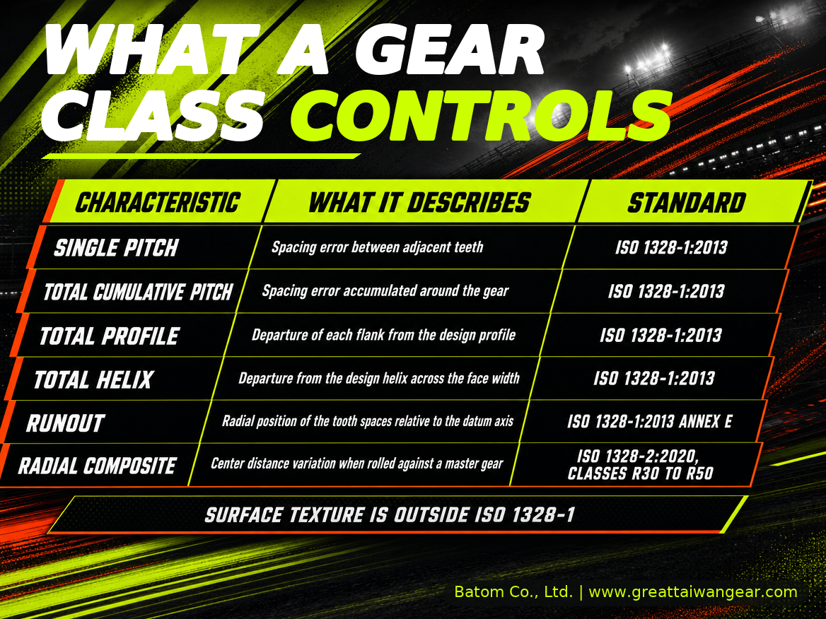
ISO 1328-1:2013 sets allowable values for a defined group of flank deviations. Knowing what each one describes makes it easier to decide which ones an application genuinely needs.
| Characteristic | What it describes | Why it matters in service | Governing document |
|---|---|---|---|
| Single pitch deviation | Spacing error between adjacent teeth | Tooth-to-tooth excitation at mesh frequency | ISO 1328-1:2013 |
| Cumulative and total cumulative pitch deviation | Spacing error accumulated around the gear | Once-per-revolution variation and angular positioning | ISO 1328-1:2013 |
| Total profile deviation | Departure of each flank from the design profile | Contact conditions and noise | ISO 1328-1:2013 |
| Total helix deviation | Departure from the design helix across the face width | Load distribution along the face | ISO 1328-1:2013 |
| Runout | Radial position of the tooth spaces relative to the datum axis | Eccentricity and center distance variation | ISO 1328-1:2013, Annex E |
| Double flank radial composite deviation | Center distance variation when rolled against a master gear | Combined effect of several errors, measured quickly | ISO 1328-2:2020 |
Runout moved into Part 1 with the 2013 edition; the 1997 edition of ISO 1328-2 had covered it. The current Part 2, ISO 1328-2:2020, applies to gears with three or more teeth and reference diameters up to 600 mm, and it now covers sector gears as well.
The scope of ISO 1328-1:2013 is broad but has limits. Its tolerance formulae apply from 5 to 1,000 teeth and reference diameters from 5 mm to 15,000 mm. Normal modules from 0.5 mm to 70 mm, facewidths from 4 mm to 1,200 mm and helix angles up to 45° are covered. Surface texture sits outside the standard, which refers readers to ISO/TR 10064-4, so flank and root roughness need a callout of their own.
Writing a Complete Gear Quality Callout
A complete callout lets every competent supplier price the same inspection effort. It also lets the buyer's incoming inspection repeat the result. ISO 1328-2:2020 notes that measurement methods, documentation of results, inspection frequency and the use of statistical methods are normally agreed between manufacturer and purchaser. Writing those points onto the drawing or the purchase specification settles them before the first lot instead of after it.
| Element | What to state | Example wording (illustrative) |
|---|---|---|
| 1. Standard and edition | The document and year that govern acceptance | ISO 1328-1:2013 |
| 2. Class | One class, or a class per parameter if they differ | Class 6 for pitch; class 5 for profile and helix |
| 3. Parameters | Which deviations are measured and accepted | Pitch, profile, helix, runout |
| 4. Method | Analytical, double flank or single flank, plus the datum axis | Analytical measurement on the drawing datum axis |
| 5. Sampling | First article scope, then lot frequency | Full first article, then an agreed lot sample |
| 6. Report | Format and data delivered with the parts | Measured vs allowable values, charts, calibration status |
The gear data block needs to be complete as well, because the tolerance values are calculated from the gear's geometry. That means the number of teeth, normal module, pressure angle, helix angle and hand, and tooth thickness or its equivalent. Any intended profile or helix modification needs its own tolerance, since a modification drawn without one leaves the inspector no basis for acceptance.
If radial composite testing forms part of acceptance, the callout should also identify the master gear or state that its specification will be agreed in writing. ISO 1328-2:2020 defines its tolerances for a product gear mated in double flank contact with a master gear, so the master's own accuracy feeds into every reading.

Matching Inspection Methods to Characteristics
No single instrument verifies every line of a callout, so the method has to match the characteristic. ISO/TR 10064-1:2019 describes measurement practice for pitch, profile, helix and tangential composite characteristics. Double flank testing is covered separately in ISO/TR 10064-2.
| Method | Verifies | Practical notes |
|---|---|---|
| Analytical measurement on a gear measuring center | Pitch, profile, helix, runout | Produces per-flank charts; the usual method for elemental deviations |
| Double flank composite test | Total and tooth-to-tooth radial composite deviation | Quick and suited to production checks; does not separate left and right flanks |
| Single flank composite test | Tangential composite deviation (transmission error) at operating center distance | Closest to running behavior; described in ISO 1328-1:2013 Annex F |
| CMM | Datums, bores, faces and positions; gear geometry with suitable software | Useful for the features that locate the gear in the assembly |
| Surface roughness measurement | Flank and root texture | Specify separately, since it is outside ISO 1328-1 |
Single flank testing deserves more attention on noise-sensitive programs. Transmission error is the small deviation of the driven gear from its theoretically correct position, and it is closely linked to gear noise and vibration. NASA Glenn Research Center installed a dedicated transmission error measurement system, noting that accurate data helps researchers understand the mechanisms behind gear noise.
Measurement uncertainty also needs a place in the conversation at fine classes. ISO 1328-1:2013 gives equipment verification and uncertainty a clause of its own. Traceability runs upward from the shop floor, too. NIST resumed gear artifact calibration in 2019 and reported uncertainties of 0.6 to 1.0 micrometers for its 2022 calibrations. Asking a supplier how its gear measuring instruments are verified, and how recently, is a fair question.
Geometric classes also say nothing about metallurgical condition. Grinding burn and surface cracks need their own inspection requirements whenever the application calls for them. During supplier qualification, it is reasonable to ask which of these checks are performed in-house and how their results are reported.
For a sense of what a published inspection footprint looks like, Batom's quality guarantee page lists Klingelnberg P-series gear measuring centers, Frenco double-flank gear rolling testers and a bevel gear engagement tester. The same list includes contour measurement, a Zeiss three-axis CMM and magnetic particle inspection. Published test-report examples cover ground, shaved, skived and power-honed gears, along with ripple analysis, hardness and non-contact measurement. Batom's commissioned inspection services add grinding burn, particle cleanliness and full-dimension gear inspection. The standard and class that apply to any specific part are still settled on that part's drawing.
What a Measurement Report Should Show
A report earns its place when someone who was not in the measuring room can check it against the drawing. A useful gear measurement report typically shows:
- Part number, drawing revision and the lot or serial number measured
- The standard, edition and class specified on the drawing
- For each parameter and each flank, the measured value, the allowable value and the result
- Profile, helix and pitch charts, with evaluation ranges and filter settings stated
- The datum axis used and the teeth measured
- Instrument identification and calibration or verification status
- Date, operator and approval
For production lots, individual reports are usually complemented by trend data on the characteristics that matter most. The acceptance threshold for capability indices comes from the customer's own quality requirements, so it belongs in the purchase specification. Each report should also tie back to the lot record, which lets a measurement be traced to the material and heat-treatment batch it came from.
There is more on lot records, batch tracking and material certificates in the aerospace gear traceability guide.
Charts matter because a single number hides the shape of a deviation. Two gears with the same total profile deviation can produce very differently shaped profile charts. The shape usually tells an engineer more about the finishing process than the total does.
The Cost of Over-Specifying
A class tighter than the function needs adds cost in ways that are easy to miss on the drawing. Finer classes generally call for additional hard finishing and longer measurement cycles. They also leave less room for heat-treatment distortion, and parts that land just outside the tighter band become scrap or rework.
The return on that spend is often smaller than expected. Because a class describes a loose gear, assembly effects such as shaft deflection, bearing clearance and housing alignment can dominate the running result. The ISO caution about loose-gear tolerances is a practical reminder to tie the class to the function the gear must deliver.
Where noise is the driver, the more effective lever is often the flank topology itself. Profile and lead modifications, such as tip relief and crowning, change how load and transmission error develop under torque. That is design work, and it is best settled before the class is chosen.
The EV gear micro-geometry and NVH analysis covers micro-geometry, profile modification and their effect on NVH in more depth than this section allows.
A manufacturability review of the drawing is the practical checkpoint for both questions. Batom's gear design and analysis work covers profile and lead modifications, tooth-root stress FEM, loaded tooth contact analysis and transmission error analysis. That work sits with a development team of more than 35 engineers. Reviewing the callout and the modifications together is how a supplier can point out a class that neither the finishing route nor the application requires.
Sources
- ISO 1328-1:2013 Cylindrical gears: ISO system of flank tolerance classification, Part 1 (ISO)
- ISO 1328-2:2020 Cylindrical gears: double flank radial composite deviations (ISO)
- ANSI/AGMA ISO 1328-1-B14 (ANSI Webstore)
- Back to the Future: Gear Edition (NIST)
- Gear Transmission Error Measurement System Made Operational (NASA Glenn Research Center)
About the Author
Batom Co., Ltd. Marketing Department
Batom was founded in 1981 and is headquartered in Dali District, Taichung. It brings over 40 years of experience in gear manufacture and inspection. As a Leading Precision Gear Manufacturer, its work is DFM and gear manufacturing: precision gear components machined to the customer's drawing. Its certifications include ISO 9001, IATF 16949 for automotive-grade quality control, AS9100 and Nadcap, together with ISO 14001, ISO 14064-1 and ISO 14067.
From the manufacturing side, the quality callouts that move most smoothly from quote to first article share one trait. The standard, edition, parameters and report format were settled before any cutting began. That is why this guide spends more time on wording than on tolerance values.
If you have a gear drawing and want a second opinion on whether its quality callout is complete, send it with the specified standard, class and annual volume to Batom's engineering team. You can request a drawing review and quote for your gear components, and the team will come back with manufacturability feedback on the callout.
Frequently Asked Questions
Q: What is the difference between AGMA and ISO gear quality? A: ANSI/AGMA 2015-1-A01 defined accuracy grades A2 to A11. It has been replaced by ANSI/AGMA ISO 1328-1-B14, which is identical to ISO 1328-1:2013 and defines flank tolerance classes 1 to 11. In both systems a smaller number means a tighter tolerance, but the grades are broadly aligned rather than identical, so the drawing should name the standard and edition.
Q: Is DIN 3962 still a valid gear standard? A: DIN 3962-1 from 1978 has been withdrawn and replaced by DIN ISO 1328-1:2018-03. Many legacy drawings still reference DIN classes. Before quoting, confirm with the design owner which current standard and class the requirement should translate to.
Q: What does a gear tolerance class control? A: Under ISO 1328-1:2013, a flank tolerance class sets allowable values for single pitch, cumulative pitch, total profile and total helix deviations, with runout in Annex E. Double flank radial composite deviations are classified separately in ISO 1328-2:2020, using classes R30 to R50. Surface texture is outside ISO 1328-1 and needs its own callout.
Q: How do double flank and single flank gear tests differ? A: A double flank test rolls the gear in tight mesh with a master gear and records center distance variation as radial composite deviation. A single flank test runs the gear at its operating center distance with one flank in contact and records transmission error. Double flank testing is quick and suits production checks, while single flank results relate more closely to running behavior and noise.
Q: What should a gear inspection report include? A: A useful report names the drawing revision, the standard and edition, and the specified class. It lists measured and allowable values for each parameter and flank, with charts, evaluation ranges, the datum axis, the teeth measured and the instrument's calibration status. For production lots, it should also link to the lot record so results stay traceable.