Gear Tolerance Stack-Up: Runout, Backlash and Tooth Profile in Assemblies
A gear pair can pass every check on the inspection bench and still bind, rattle or whine once it is mounted. The gears are only one part of the tolerance chain. Housing bores, bearings, shafts and operating temperature each add their own variation, and the mesh sees the sum. ISO 1328-1:2013 makes the point in its own caution: users should not apply tolerance values for unassembled gears directly to the projected performance of an assembly.
This guide follows that chain from the housing to the tooth flank. It starts with what accumulates in a mesh and why runout makes backlash cycle. It then compares worst-case and statistical stack-ups, and closes with datums, profile deviations and the drawing itself. It is written for design and sourcing engineers reviewing drawings for custom gear programs before an RFQ goes out.
What Accumulates in a Gear Mesh
Backlash is the working clearance between mating teeth. NASA Reference Publication 1152, Gearing, defines it as the difference between tooth thickness and tooth space measured along the pitch circle. The report names two ways to create it: cut the teeth slightly thinner, or set the center distance slightly greater. It also sets the design condition. Backlash must permit free action under the most severe combination of manufacturing tolerances and operating temperature variations.
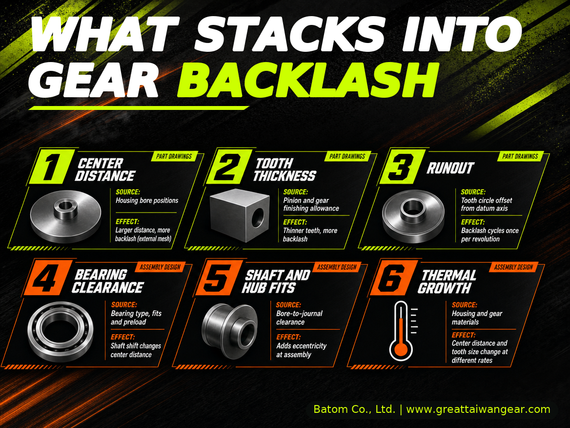
That condition is what a stack-up has to protect. Six contributors usually decide whether it holds.
| Contributor | Where the variation comes from | Effect on backlash |
|---|---|---|
| Center distance | Housing bore positions and their tolerance | On an external mesh, a larger center distance increases backlash |
| Tooth thickness, pinion and gear | Finishing allowance on each gear | Thinner teeth increase circular backlash one for one at the pitch circle |
| Radial runout and eccentricity | Tooth circle offset from the datum axis | Backlash rises and falls once per revolution |
| Bearing internal clearance | Bearing type, fits and preload | The shaft can shift under load, changing the effective center distance |
| Shaft and hub fits | Clearance between a bore and its journal | Adds eccentricity at assembly that gear-only inspection cannot see |
| Thermal growth | Housing and gear materials, temperature range | Center distance and tooth size change at different rates |
The first three sit on part drawings. The last three are set by the assembly design, so inspecting a gear on its own cannot confirm them.
The Center Distance Relation
One relation from the NASA report, its equation (7), does most of the conversion work. If the center distance between two external gears increases by ΔC, circular backlash increases by ΔB = 2 × ΔC × tan φ. Here φ is the operating pressure angle, or the operating transverse pressure angle for helical gears. For an internal mesh, such as a pinion running inside a ring gear, the same equation gives a decrease in backlash for an increase in center distance.
The following numbers are illustrative, not design values. Take a spur pair with a 20° pressure angle and a center distance 0.020 mm over nominal. It gains about 2 × 0.020 × 0.364 ≈ 0.015 mm of circular backlash. At 20°, the factor 2 tan φ is about 0.73, so a center distance tolerance moves circular backlash by roughly three quarters of the same tolerance on tooth thickness.
How Runout Turns Backlash Into a Cycle
Runout is usually measured by seating a ball or pin in each tooth space and recording the spread of radial readings around the gear. The code of inspection practice for runout, radial composite deviation, tooth thickness and backlash is ISO/TR 10064-2. Allowable runout values now sit in ISO 1328-1:2013, which brought runout evaluation back from Part 2.
The effect on backlash follows from simple geometry. Suppose the tooth circle is offset from the axis of rotation by an eccentricity e. Over one revolution, the effective center distance to the mating gear swings between roughly a − e and a + e, where a is the nominal center distance. Applying the NASA relation, circular backlash on an external mesh swings by about ±2 × e × tan φ. The mesh is tightest where the high side of the gear faces its mate. A ball or pin runout check on a purely eccentric gear reads about 2e, so halve a runout value before using it as e.
When both gears are eccentric, each cycle runs at its own shaft speed. The tightest condition occurs only when both high sides reach the mesh together, so a single backlash reading after assembly can easily miss it. A more useful check marks the high side of each gear, preferably from a runout reading taken on its mounted shaft. It then turns the pair until both marks meet at the mesh, or come as close as the tooth counts allow, and records the clearance there and at several other positions.
ISO 1328-2:2020 covers double flank radial composite testing, in which the product gear rolls in tight mesh with a master gear. Runout and tooth thickness variation then show up together as center distance movement. The standard notes that tooth-to-tooth readings can be greatly influenced by runout, especially on gears with low numbers of teeth. It also cautions that a class from double flank testing does not correlate with the class from the elemental methods of ISO 1328-1. Batom's published inspection equipment includes Klingelnberg P-series gear measuring centers, Frenco double-flank gear rolling testers and a Zeiss 3-axis CMM.
Worst Case or Statistical: Choosing the Stack-Up Method
A worst-case stack-up adds every contributor at its limit. The result holds as long as each part meets its drawing, but it is conservative. A statistical stack-up, usually root sum of squares (RSS), takes the square root of the sum of the squared contributions. It relies on the variations being independent, so that extreme values rarely coincide.
Lecture notes on statistical tolerancing from the University of Washington frame the tradeoff clearly. Worst-case tolerancing can be quite costly, because dividing an assembly tolerance across many parts produces very tight item tolerances. Statistical tolerancing concerns mass production rather than custom-made items, and it assumes the parts in an assembly are chosen at random.
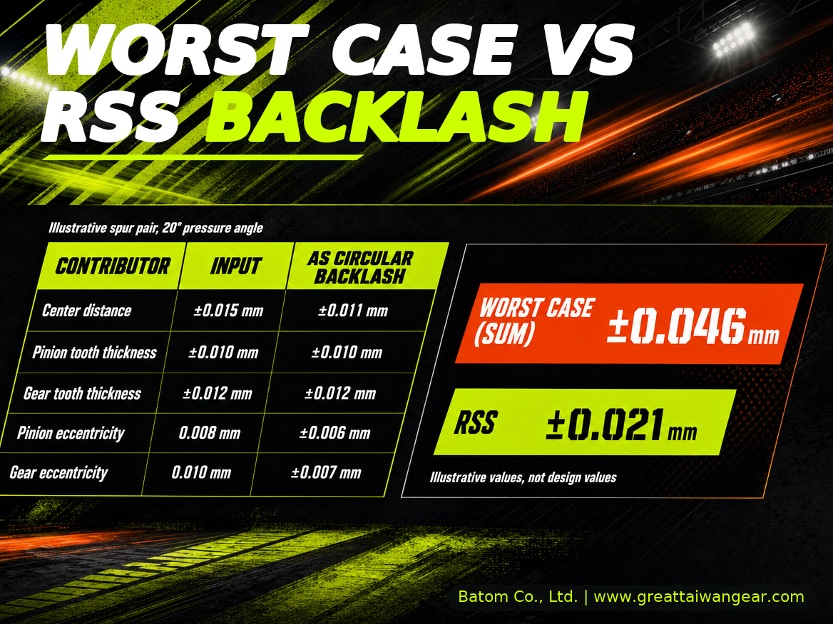
The table below runs both methods on one illustrative spur pair at a 20° pressure angle. Every value is an example for comparing methods, not a design value. Each contributor is converted to circular backlash before stacking.
| Contributor (illustrative) | Input variation | Converted to circular backlash |
|---|---|---|
| Center distance | ±0.015 mm | ±0.011 mm (2 × 0.015 × tan 20°) |
| Pinion tooth thickness | ±0.010 mm | ±0.010 mm |
| Gear tooth thickness | ±0.012 mm | ±0.012 mm |
| Pinion eccentricity | 0.008 mm | ±0.006 mm (2 × 0.008 × tan 20°) |
| Gear eccentricity | 0.010 mm | ±0.007 mm (2 × 0.010 × tan 20°) |
| Worst case (sum) | ±0.046 mm | |
| RSS | ±0.021 mm |
In this example the statistical band is less than half the worst-case band. That gap is the case for statistical methods, and it is also where their risk sits.
One caution applies to the eccentricity rows. In service, the high sides of both gears eventually reach the mesh together on most tooth-count combinations, so within one assembly those two terms add. Treat them like the persistent effects in the Washington notes, and add them arithmetically in a minimum-backlash check. The RSS row here only illustrates the method.
When Each Method Fits
Worst case suits the minimum-backlash check on low-volume, custom or safety-relevant assemblies. Binding cannot be accepted there, and the parts are not a random draw from a large, stable population. It also suits stacks with few contributors. The Washington notes point out that one large term can dominate the sum and undermine the normal approximation RSS depends on.
Statistical methods suit high-volume builds from capable, centered processes, where the question is the spread of backlash across many assemblies. The same notes add a caveat that matters for gears. Mean shifts, such as a tooth thickness process that runs consistently toward one limit, are persistent effects. They should be added arithmetically on top of the RSS variation. The two methods can also be combined: worst case to protect the minimum clearance, and a statistical stack-up to estimate the expected spread.
Datums: Measure the Gear About the Axis It Runs On
ISO/TR 10064-3 opens its section on gear blanks with a statement worth keeping on every design review checklist. Tooth accuracy values such as profile deviation and pitch deviation are only meaningful relative to a particular axis of rotation. If the axis used during measurement changes, the measured values change too.
That is why the drawing has to define a datum axis. ISO 1328-1:2013 defines it as the axis to which the pitch, profile and helix tolerances are defined, set by the datum surfaces. ISO/TR 10064-3 notes that this is often conveniently achieved by making the datum axis coincide with the functional axis, using the mounting surfaces as datum surfaces. The report describes three methods. Two short cylindrical or conical surfaces, such as bearing seats, can define it. So can one long bore represented by a fitted arbor, or one short cylinder combined with a perpendicular end face.
Manufacturing sometimes works from a different axis, such as centers on a shaft. In that case ISO/TR 10064-3 requires the other axes to be related to the datum by tolerances, which adds a link to the tolerance chain. ASME Y14.5 provides the drawing language for those relationships, including runout controls applied to a datum axis.
Datums also have to survive heat treatment. Hardening can distort a gear, so the drawing should make clear which datum surfaces the final gear data refers to, and in what condition they are measured.
Profile and Helix Deviations: Contact Pattern Before Clearance
Profile and helix deviations matter mainly for how the teeth carry load. A profile deviation disturbs the smooth transfer of motion between teeth and shows up as transmission error, a common source of gear whine. A helix deviation, or a lack of parallelism between the two shafts, moves the contact toward one end of the face width. ISO/TR 10064-3 gives recommendations for parallelism of axes alongside center distance.
The link to the stack-up is indirect. Misalignment from housing bores, bearing clearance and shaft deflection adds to whatever helix deviation the gear already carries. The contact pattern therefore depends on the assembly as much as on the gear.
When the expected misalignment and deflection are known, the usual response is flank micro-geometry, such as tip relief and crowning. Batom's published gear design and analysis capability includes profile and lead modifications, loaded tooth contact analysis and transmission-error analysis. Sizing those modifications is a load-dependent design step of its own.
Engineers working through profile and lead micro-geometry will find more detail in the EV gear micro-geometry and NVH guide.
Allocating the Backlash Budget
Start from the assembly requirement and work back toward the parts. A workable sequence looks like this:
- Set the limits. Define the minimum backlash that must remain at the tightest combination of tolerance and temperature, and the maximum the application can accept. NASA RP-1152 notes that backlash should be small in positioning control systems and can be generous for single-direction power gearing.
- List every contributor. Include the housing, bearings and fits alongside the gears, and note which drawing owns each one.
- Convert to backlash. Use 2 × ΔC × tan φ for center distance and eccentricity, and a one-for-one conversion for circular tooth thickness. Convert span or over-pins tolerances to circular tooth thickness first, per ANSI/AGMA 2002-D19.
- Stack both ways. Check the minimum with worst case, and estimate the spread statistically if the build volume supports it.
- Rebalance before tightening the teeth. Check whether housing and blank tolerances can absorb part of the budget first.
The last step reflects a recommendation in ISO/TR 10064-3. Holding blank and housing tolerances tight, consistent with the manufacturing facilities available, lets the gears be made to less exact tolerances. The report adds that this usually produces the most economical overall design.
Temperature belongs in the first step. When the housing and gears are made from materials with different expansion rates, center distance and tooth size change by different amounts as the assembly warms. Depending on the material pairing, minimum backlash may occur hot or cold. NASA RP-1152 records that in early conformal gear designs, thermal expansion in gearcases and shafts was enough to change center distances and lead to early failure.
Multiple-mesh arrangements such as planetary gear sets add one more condition. NASA RP-1152 advises keeping backlash and backlash tolerances as nearly equal as possible at each mesh to ensure equal load distribution.
What the Gear Drawing Should Carry
A stack-up only holds if the drawings carry the information it assumed. For each gear, that usually means the items below.
| Drawing item | Why the stack-up needs it |
|---|---|
| Gear data block: module, number of teeth, pressure angle, helix angle, profile shift | Defines the nominal geometry every conversion starts from |
| Tooth thickness with tolerance and measurement method (span, over pins or balls) | Sets the nominal backlash and one of its main contributors |
| Mating center distance and its tolerance, as a reference | Shows the gear maker the backlash intent |
| Datum axis defined by functional mounting surfaces | Ties runout, profile and helix values to the running axis |
| Runout tolerance to that datum | Controls the once-per-revolution backlash cycle |
| Flank tolerance class with the standard and edition, for example ISO 1328-1:2013 | Avoids ambiguity between editions |
| Double flank radial composite tolerances, if used, per ISO 1328-2:2020 | Checks runout and thickness variation together against a master gear |
| Profile and lead modifications, if any | Separates intended micro-geometry from deviation |
Stating the edition matters because the standards have moved content between parts. ISO 1328-2:2020 records that runout evaluation moved from that document to ISO 1328-1:2013, and that its double flank classes do not correlate with Part 1 classes. For tooth thickness, ANSI/AGMA 2002-D19, Tooth Thickness and Backlash Measurement of Cylindrical Involute Gearing, is the AGMA reference.
The backlash requirement itself belongs on the assembly drawing, because only the assembly determines it. A gear drawing that states the mating center distance and the datum scheme lets a manufacturer's engineers review manufacturability against the real function. Batom's engineering team of more than 35 engineers prepares process plans from prototypes through PPAP and mass production, and begins production planning during sample development.
Sources
- ISO 1328-1:2013, Cylindrical gears: ISO system of flank tolerance classification, Part 1
- ISO/TR 10064-2:1996, Cylindrical gears: Code of inspection practice, Part 2
- ISO/TR 10064-3:1996, Cylindrical gears: Code of inspection practice, Part 3
- NASA Reference Publication 1152, Gearing (Coy, Townsend and Zaretsky)
- University of Washington, Statistical Tolerancing lecture notes (F. Scholz)
About the Author
This article was written by the Batom Co., Ltd. Marketing Department. Batom was founded in 1981 and is headquartered in Dali District, Taichung. It has over 40 years in gear manufacture and inspection as a Leading Precision Gear Manufacturer. Its work is DFM and gear manufacturing, machining precision gear components to the customer's drawing. Seen from that side of the drawing, a tolerance stack-up is a handoff between two engineering teams. The gear maker controls tooth thickness, runout and flank accuracy about a datum. The designer decides which running axis that datum must represent. Stack-ups hold up best when the drawing makes that handoff explicit and the numbers on it trace back to the assembly requirement.
If your assembly already defines the center distance, the backlash limits and the datum scheme, the gear drawing is the next step. Send your gear drawings for a manufacturability review by Batom's engineering team, with the tooth thickness callout and runout tolerance marked. The review then starts from the same stack-up your design assumes.
Frequently Asked Questions
Q: What is gear tolerance stack-up? A: Gear tolerance stack-up is the combined effect of every tolerance that changes how two gears mesh in an assembly. It includes center distance, tooth thickness, runout, bearing clearance, shaft and hub fits, and thermal growth. ISO 1328-1:2013 cautions against predicting assembly performance from the tolerances of unassembled gears alone.
Q: How does center distance affect gear backlash? A: For external gears, a larger center distance increases backlash. NASA Reference Publication 1152 gives the change in circular backlash as 2 × change in center distance × tan (operating pressure angle), using the operating transverse pressure angle for helical gears. For an internal gear mesh, an increase in center distance decreases backlash instead.
Q: Does gear runout change backlash? A: Yes. Eccentricity swings the effective center distance once per revolution, so backlash cycles between a minimum and a maximum. The tightest point occurs when the high sides of both gears meet at the mesh, which a single full turn may not reach. Mark each gear's high side and check backlash with both marks at the mesh as well as at several other positions.
Q: Should backlash stack-ups use worst case or RSS? A: Worst case is the safer basis for minimum backlash on low-volume, custom or critical assemblies. RSS suits high-volume builds from centered, independent processes, with persistent mean shifts added arithmetically. The two can be combined, using worst case for the minimum limit and RSS for the expected spread.
Q: What datum should gear runout reference? A: Runout and other tooth accuracy values should reference the datum axis defined on the gear drawing. ISO/TR 10064-3 notes that this is often conveniently achieved by making the datum axis coincide with the functional axis, using the mounting surfaces as datum surfaces. If manufacturing uses another axis, it must be related to the datum by tolerances.